PCBピンコネクター:端子ピン、ヘッダーピンなどについて
プリント基板(PCB)ピンとは?
PCBピンは、コンポーネントと回路基板アセンブリ間の多くの最新の電気相互接続システムの小さな構成要素です。これらは、コネクタピンを回路基板に直接取り付け、ワイヤ、ケーブル、または信頼性の低いはんだ付けワイヤを使用する専用の標準コネクタなしで相互接続できるように開発されました。個別には、これらはコンポーネントをボードに経済的、機能的、カスタム接続したり、ボード間で接続したりできるように、アレイに取り付けることができる小型の金属ピンです。製品での使用の増加は、より小型の電子コンピューティング、制御、通信デバイスの無限の設計によって推進されています。現在、PCBピンは、多くのサイズ、形状、材料、構成があります。
PCBピンの使用方法
最も基本的なPCBピンは、金属製のチューブ型オスコネクタで、個別やグループで、通常はスルーホール技術を使用して回路基板に直接取り付けられます。これらはまた、ピンヘッダーと呼ばれるプラスチックハウジングを有するアレイの一部として使用することもできます。
コネクタとして、PCBピンは、接続を行うためにピンが挿入されるレセプタクルまたはソケットを使用する必要があります。ピンとヘッダーの嵌合は、1つのコンポーネントまたはPCBの機能をシステム内の別のコンポーネントに接続するように電気的および機械的に動作する固体接続を形成します。これにより、ストレート接続やライトアングル接続など、いくつかの設計上の考慮事項も考慮できます。
設計でPCBピンを使用する利点とは?
電子システム内のコンポーネントは、いくつかの方法で接続することができ、その一部は非常に洗練されています。信号効率が高く製造に優しい相互接続を必要とする現代の設計においては、PCBピンの勝算は難しくなっています。製品設計でPCBピンが提供できる利点を以下に示します。
- 電気回路の単純な導電経路を有効にします
- 複数の接続が可能
- さまざまなボード構成に簡単に適合
- 嵌合ソケットとともに、PCBに機械的補強を追加することも可能
- 幅広いバリエーションにより、幅広い用途でカスタマイズが可能
- 信号損失なしで、信頼性が高く、安定した安全な接続を提供
- 衝撃、振動、温度の揺れに強い耐久性のある設計
- メンテナンスが少なく、修理やアップグレードのための交換が簡単
- 他の接続ソリューションと比較してコスト効率が高い
- 挿入力が低いため、挿入や取り外しが容易
- 高密度相互接続を可能にするPCB上の最小限の不動産を占有
- 高速データ伝送と電力信号または音声信号が可能
このリストは少し長くなる可能性があるため、ここで止めておきましょう。お客様のニーズに応じて、設計にPCBピン技術を使用すると、製品やシステムのパフォーマンスに対して効果的に追加できる複数の機能を提供できるかもしれません。
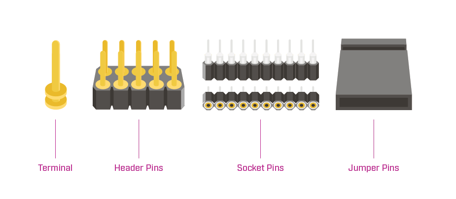
PCBピンの一般的なタイプは何ですか?
PCBピン技術が成長するということは、さまざまなタイプやスタイルが開発されているということです。PCBピンの基本的なタイプは次のとおりです。
- 端子ピン: 個々のPCBピンの別名
- ヘッダーピン: プラスチックベースで囲まれた個別のピン付きのオスコネクター
- ソケットピン: PCBピンが挿入されるリセプタクルピン
- ジャンパーピン: テスト、デバッグ、または設計変更に役立つ回路基板上の接続をブリッジするために使用される小型コネクタ
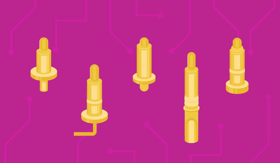
PCBピンの一般的なスタイルは何ですか?
さまざまなアプリケーションや製造プロセスに対応する多数のPCBピンスタイルがあります。これらの個別のピンスタイルには、以下が含まれます。
- シングルエンドまたはダブルエンド: ピンの一方の端または両端で接続可能
- 単一行または二重行: 1列のピンまたは2列
- エッジマウント: エッジに取付けられ、回路基板と平行
- ネイルヘッド: 釘のような平坦な顔の頭の上のピン
- はんだカップ: ワイヤをしっかりと保持し、はんだの流れを容易にする、片端に凹面スカラップ形状のカットアウトが付いた中空ピン
- 溝付き: ワイヤの挿入とはんだ付けが容易な、垂直スロットがカットされているピン
- タレット: ワイヤーラップまたははんだ接続を容易にする、またはテストポイントとして使用する、1つ以上の隆起した円形領域(ショルダー)を持つピン
- ワイヤークリンプ&ラップ: ワイヤーを巻き付けてはんだ付けできる角型ピン
- ワイヤー終端: 特定のワイヤサイズを受け入れ、はんだ付けを許容しない中空ピン(圧着端子とも呼ばれる)
- シュラウド付き: シュラウド付きピン、または組み立て、挿入、取り外し時にピンを保護するコネクタ本体の隆起した部分
- ポゴと磁気ポゴ: 内部圧縮接続接点付バネ付ピンで、磁化も可能です。詳細については、ポゴピンブログをご覧ください。
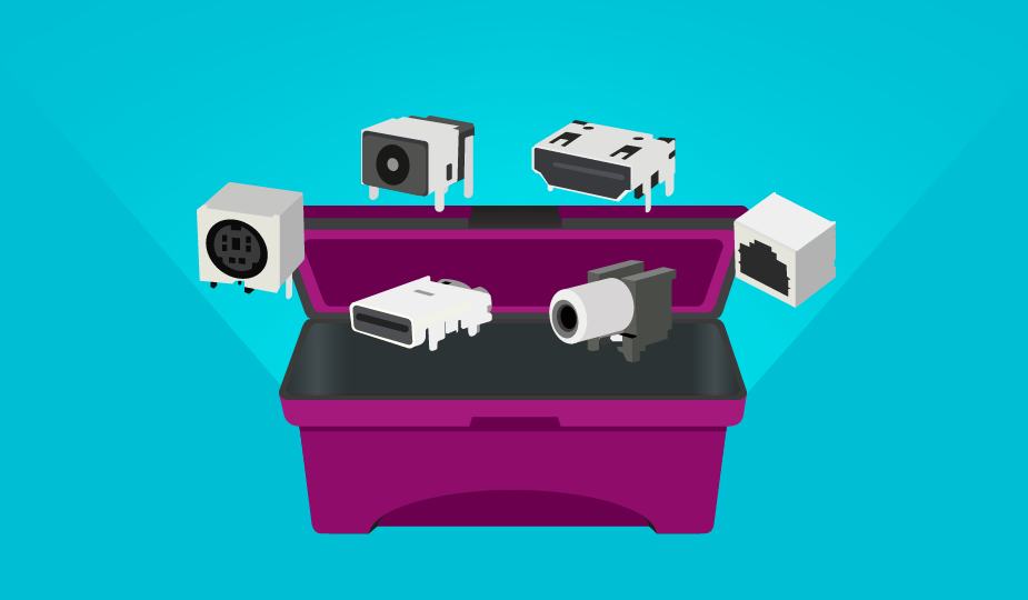
PCBピンと標準コネクタの使用
現代の電子システムのボードレベルの設計に関しては、スペースがすべてです。製品性能の未記述の法則は、時間の経過とともにデバイスの機能が向上する一方で、フットプリントがますます小さくなるということです。
標準的な電子コネクタは、特定の用途に最適ですが、通常は、高密度のボード上の利用可能な不動産に適応するように特別に設計されたピン駆動コネクタの省スペース能力とは競合しません。円形コネクタは、持つ接点の数が比較的制限されています。標準のD-subコネクタは最大約50接点まで接続でき、高密度バージョンでは密度がやや高くなります。しかし、集積回路デバイスには100以上のピンがあり得ると考えると、問題が見え始めます。
標準コネクタは、一度回路基板に取り付けられると、まったく新しい基板を開発せずに新しい設計で交換または交換することも困難です。PCBピンは、最新のアセンブリ機器によって大規模なアレイに簡単にグループ化でき、複数の嵌合サイクルを通じて安定して安全であるため、相互接続の課題に最適なソリューションとなります。
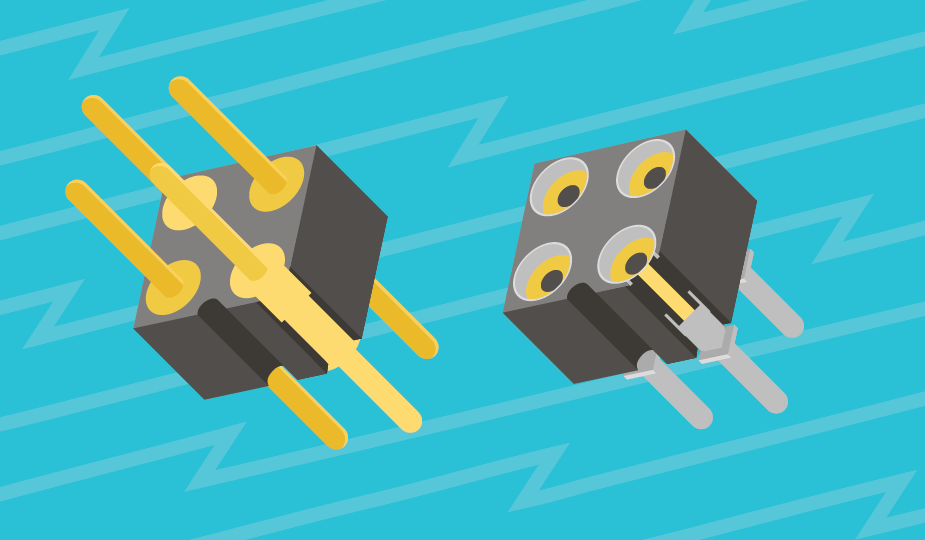
PCBピンの取り付け方法
PCBピンは、いくつかの異なる方法で設計に組み込むことができます。それらを回路基板に取り付けるために使用される基本的な技術は、プレスフィット、スウェージ、圧着、またははんだ付けです。これらの技術はそれぞれ、アプリケーションのニーズに応じて、ボードへのピン接続のさまざまな強度を提供します。PCBピンには、以下を含む標準的な取り付けスタイルもあります。
- サーフェイスマウント: ボードの上部にはんだ付け
- スルーホール: ボードに差し込み、はんだ付け
- ワイヤーマウント: 止めねじまたはクランプを使用して裸線接続を交換する場合に使用します
- フリーハンギング: ワイヤーまたはケーブル同士の接続に使用
設計のためのPCBピンの指定方法
すべての電子部品と同様に、設計に必要な仕様と性能を確定する必要があります。PCBピンでは、詳細は以下の通りです。
- 物理的: リードサイズ、ピン直径、ピン方向(垂直、水平、または直角)、取付穴サイズ、基板厚、ピン形式(丸型、正方形、または長方形)、電流および電圧定格、寸法精度、ピン密度
- コンタクト材料: (通常は真鍮、青銅、銅、ニッケル)
- メッキ: 銅、金、銀、スズ、ニッケル、パラジウム、鉛
- 製造プロセス: ピンの挿入とボードへの取り付け方法
また、過酷な環境条件や腐食性動作など、追加のコネクター機能を必要とするその他の要件がある場合もあります。
PCBピンの一般的なアプリケーションとは?
PCBピン技術は、コンピュータ、医療機器、テスト機器、通信機器、民生用電子機器、自動車エレクトロニクス、産業オートメーションシステム、航空宇宙、防衛など、幅広い業界やアプリケーションで使用されています。
PCBピン技術は、コスト効率が高く、効率的で、適応可能な相互接続ソリューションが製品設計に必要な場合は、最適なソリューションとなるかもしれません。
概要
PCBピンコネクターは、多くのさまざまなアプリケーションのニーズにうまく適応する、実績のある相互接続技術です。これらは、省スペースで、テストが簡単、修理も簡単な効率的で安全な接続を提供します。PCBピンコネクターは、プロトタイピングとボード開発における役割とともに、多くの産業での電子製品にわたる幅広い製造用途があり、相互接続のニーズに対するエレガントなソリューションとなります。
主な取り組み
- プリント基板と他のデバイス間の機械的接続と電気的接続を提供するPCBピンは、必須コンポーネントです。
- ストレートピン、ライトアングルピン、スタッカブルヘッダーなど、さまざまなタイプのPCBピンがあり、それぞれ異なる設計要件に適しています。
- 材料の選択とメッキのオプション(金やスズなど)は、導電率、耐久性、耐食性に影響を与えます。
- ピッチサイズと取り付けスタイル(スルーホールとサーフェイスマウント)は、アプリケーションに適したPCBピンを選択する上で重要な要素です。
- PCBピンは、家電製品から産業用制御システムまで幅広いアプリケーションで広く使用されており、信号や電力の伝送を容易にします。
- 適切なPCBピンを選択することで、信頼性の高い電気的接触、機械的安定性、組み立てや修理の容易さが保証されます。
 タグ:
タグ:
その他のリソース