パルス幅変調(PWM):これがどのように機能し、なぜ電子機器に不可欠か
パルス幅変調とは?
パルス幅変調(PWM)は、印加された電気信号を効率的に細分化して別の部分に分割することで、印加された電気信号の平均電力を低減する制御方法です。PWMは、デジタルソースを使用してアナログ信号の平均振幅を制御します。
もっと基本的なレベルでは、変調は、デバイスやシステムに対して制御したり影響を及ぼしたりします。電子機器においては、変調は負荷に送達される電気信号の平均電力、または振幅を制御するためにデータを電気信号に変換する(または情報を符号化する)プロセスのことです。これは、モーターや電源の制御、オーディオの増幅、照明の制御、バッテリー充電などのタスクに有用です。
パルス幅変調(PWM)、振幅変調(AM)、周波数変調(FM)は、信号の見かけの振幅や周波数を制御するために使われる最も一般的な3つの方法ですが、本ブログではPWMに焦点を当てていきます。
パルス幅変調の仕組み
前述のように、パルス幅変調は、負荷に供給される平均電流と電圧を制御することで信号を修正します。これは、電源と負荷の間のパターンで、トランジスタのオン/オフ(高電圧状態と低電圧状態を切り替える)を迅速に切り替えることで行われます。情報は、高信号と低信号の持続時間を変更することで付与されます。
実際、PWMは、オン/オフの切り替え中にデバイスが全定格電圧を受け取る時間を変更することで、デバイスに供給される電気エネルギーの量を減らします。信号のオンタイムが増減すると、信号の平均電圧も増減します。PWMには、その動作を説明する 2 つの主要コンポーネント、デューティサイクルと頻度があります。
デューティサイクルとは?
デューティサイクルは、信号がアクティブまたはオンのときの単一周期またはフルオン/オフサイクルの割合です。デューティサイクルは、ある期間中に信号がオンになっている時間のパーセンテージ(%)として表されます。一例として、オン状態が3ミリ秒、オフ状態が1ミリ秒のデジタル信号は、負荷サイクル75%、ミリ秒の期間4、250Hzの周波数です。
デューティサイクルは、ある期間内のパルスのオンタイムを効果的に決定するために、調整によって、信号が高い時間対低い時間の割合を変化させることによって、デバイスに供給される電力を制御することができます。つまり、デューティサイクルの調整により、電圧を変更することなく、デバイスを正確に制御できるのです。デューティサイクルは、多くの場合デバイスの電圧と周波数が設定され一定に保たれることから、制御することができる唯一の信号値です。発熱体などの電力供給を制御するためにPWMを使用する設計では、デューティサイクルを測定することは、システムが適切な電力レベルで動作していることも示しています。
スイッチング周波数とは?
スイッチング周波数は、特定の期間に何かが繰り返される速度です。今回の場合、基本的には、スイッチが1秒あたりオン/オフになる頻度(スイッチング速度)を指します。周波数は通常、ヘルツ(Hz)で表されます。
負荷を制御するには、特定の負荷やアプリケーションに応じてPWMスイッチング周波数を慎重に選択する必要があります。アプリケーションに対して周波数が高すぎると、機械制御コンポーネントの故障につながる可能性があります。アプリケーション対して周波数が低すぎると、負荷の振動や音響ノイズが発生することがあります。例えば、周波数は、ある電気モータに対して低く設定することができますが、LEDのような固体デバイスに対しては、かなり高く設定する必要がある場合があります。
PWMを使用することの利点は?
パルス幅変調の主な利点は、スイッチングデバイスでの電力損失が最小限になることによって効率が高くなることです。オフ状態では電流はほとんどなく、オン状態で負荷に電力を送りながらスイッチ間での電圧の降下がないため、電力損失は非常に低くなります。PWMを使用することのその他の利点は次のとおりです。
- PWMのスイッチングの性質上、リニアレギュレータよりも発熱が少ない
- デジタルシステムとの互換性
- リニアレギュレータと比較すると、デバイスの制御における電力効率が優れている
- デューティサイクルの調整による平均出力電圧や電流の正確な制御
- 設計の簡素化により、他の制御方法よりも複雑な回路やフィードバック機構の必要性が少ない
- さまざまなデバイスを制御する幅広いアプリケーション
PWMを使うことの欠点は?
パルス幅変調は、エレガントな制御ソリューションでありながら、設計上の課題がないわけではありません。PWMを使うことの欠点には、次のようなものがあります。
- より高い周波数では、より大きなスイッチング損失が発生する可能性がある
- PWMは電圧スパイクを引き起こす可能性がある
- PWMを使用すると、EMI、高調波歪み、電気ノイズが回路に入り込む可能性がある
- 高出力アプリケーションの場合、PWM回路は複雑になり得る
スイッチング周波数とデューティサイクルのサンプル
周波数とデューティサイクルは、制御アプリケーションではPWMの2つの主要なコンポーネントであるため、それぞれがその特定のアプリケーションに適合する必要があります。以下で詳しく説明する製品エリアの各例は、Same Skyから入手できます。アプリケーションによって、注意すべき点は異なります。
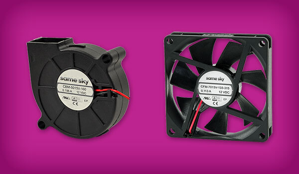
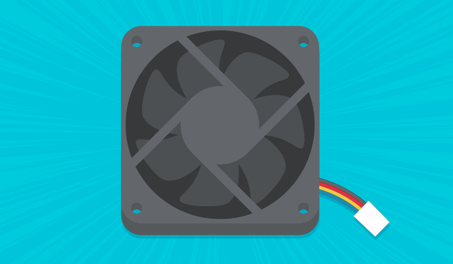
ファンの推奨スイッチング周波数とデューティサイクル
ほとんどのファンアプリケーションでは、20 kHz~ 25 kHzのPWM周波数と、0%(オフ)~100%(フルスピード)の可変デューティサイクルを使用してファン速度を制御します。通常、より高い周波数を使用すると、ファンの動作がスムーズになり、可聴ノイズが少なくなります。推奨PWM周波数とデューティ・サイクルの範囲は、通常、ファンの最適な性能を確保するためにファンの製造元によって指定されています。Same SkyのACファンとDCファンの全ラインナップをご覧ください。
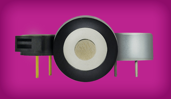
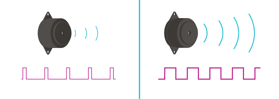
ブザーの推奨スイッチング周波数とデューティサイクル
ブザーの制御では、PWM周波数は通常、1 kHz~10 kHzに設定されています。これは、人間が聴こえる可聴周波数範囲が通常、20 Hz~20 kHzだからです。デューティサイクルを調整するとブザーの音量が制御されますが、通常、デューティサイクルの50%は、音量と歪みのバランスを生み出します。ほとんどの設計では特定の狭い周波数範囲が必要なため、ブザーメーカーに確認することが賢明です。50%のデューティサイクルは、一般的にバランスの取れた音を出します。Same Skyのオーディオブザーの包括的なラインをご覧ください。
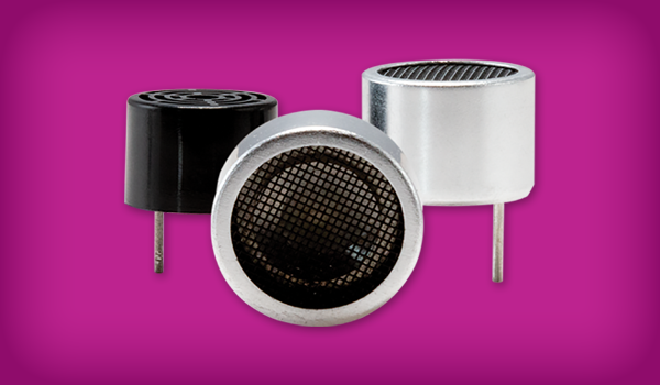
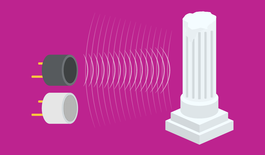
超音波センサの推奨スイッチング周波数とデューティサイクル
超音波センサの最も一般的なPWM周波数範囲は、明確な超音波パルスを確保するために50%のデューティサイクルで20kHz~400kHzです。最良の結果を得るために、メーカーの推奨事項を必ず確認してください。Same Skyの超音波センサ製品ラインをご覧ください。
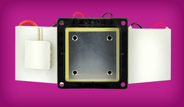
ペルチェ装置に推奨されるスイッチング周波数とデューティサイクル
冷却のためにペルチェデバイスを制御するためにPWMを使用するには、通常、所望の冷却量を制御するためにデューティサイクルが設定されている300Hz~3kHzの周波数が必要です。推奨については、必ずメーカーにお問い合わせください。Same Skyのペルチェデバイス製品ラインナップをご確認ください。単段式および多段式のペルチェモジュールに加え、ペルチェ冷却ユニットもご用意しております。
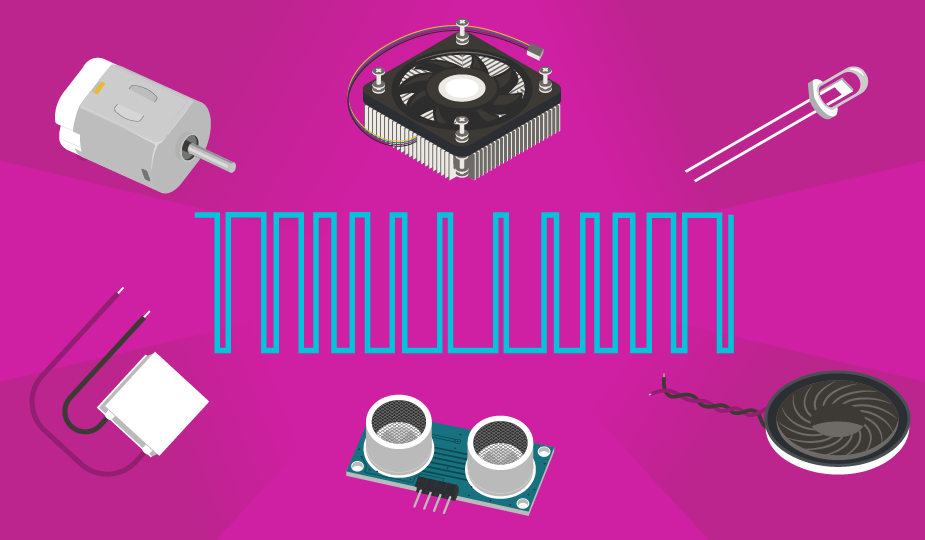
PWMの一般的なアプリケーションとは?
パルス幅変調技術は、幅広い業界やアプリケーションで使用できる制御方法です。ファン、ブザー、超音波センサー、ペルチェデバイスについては、すでに言及しました。その他のアプリケーションには以下が含まれますが、これらに限定されません。
- LEDと白熱灯の制御
- ロボット用サーボモーター速度と角度制御
- ソーラーパネルの出力制御
- 電源出力電圧の制御
- DCモータ速度の制御
- 加熱素子の調節
- バッテリー充電の管理
- オーディオ・アンプの信号生成
- 通信でのメッセージ・エンコーディング
- 自動車のスロットルと燃料インジェクターの制御
概要
変調とは、デバイスやシステムに対する制御を適用することです。特にパルス幅変調は、様々な電子機器の電力を制御するために使用され、効果的かつ効率的な方法です。他の制御技術と比較して、パルス幅変調は正確な制御と低消費電力動作を可能にし、デジタル信号を使用してアナログのような制御を行う多くのアプリケーションで使用されています。
パルス幅変調に関する技術的な詳細については、こちらのCircuitBreadの関係者やパートナーたちが投稿したPWMの記事をご覧ください。
主な取り組み
- パルス幅変調(PWM)は、信号のオン/オフを高速に切り換え、オンタイム(デューティサイクル)の割合を変化させることでアナログ電力を制御するデジタル形式の方法です。
- デューティサイクル(%で表記)は、各サイクルで信号が「オン」に留まる時間を決定し、デバイスに供給される平均電圧と電力を直接制御します。
- スイッチング周波数(Hz単位)は、オン/オフサイクルの反復速度です。ノイズ、非効率、またはコンポーネントの損傷を避けるため、正しい周波数をアプリケーションに一致させる必要があります。
- PWMには、高いエネルギー効率、熱の低減、デジタル・システムの互換性、正確な電力制御などのメリットがあり、組み込み設計や電力重視設計に最適です。
- 欠点としては、スイッチング損失、EMI、電圧スパイク、高出力アプリケーションで複雑になり得ることなどがあります。
- 一般的なPWMアプリケーションは、ファン、ブザー、超音波センサー、ペルチェモジュールからLED照明、モーター、バッテリー充電器、オーディオシステム、自動車制御システムに至るまで多岐にわたります。
- 最適な性能を得るためには、デューティサイクルと周波数を適切に選択することが重要です。必ずコンポーネントのデータシートや製造元のガイドラインを参照してください。
 タグ:
タグ:
その他のリソース